Home
Company
Product
News
Contact
Classification:
Hotline:
0318-8888331
Detailed introduction
Graphic Details
Previous Page
None
Next Page
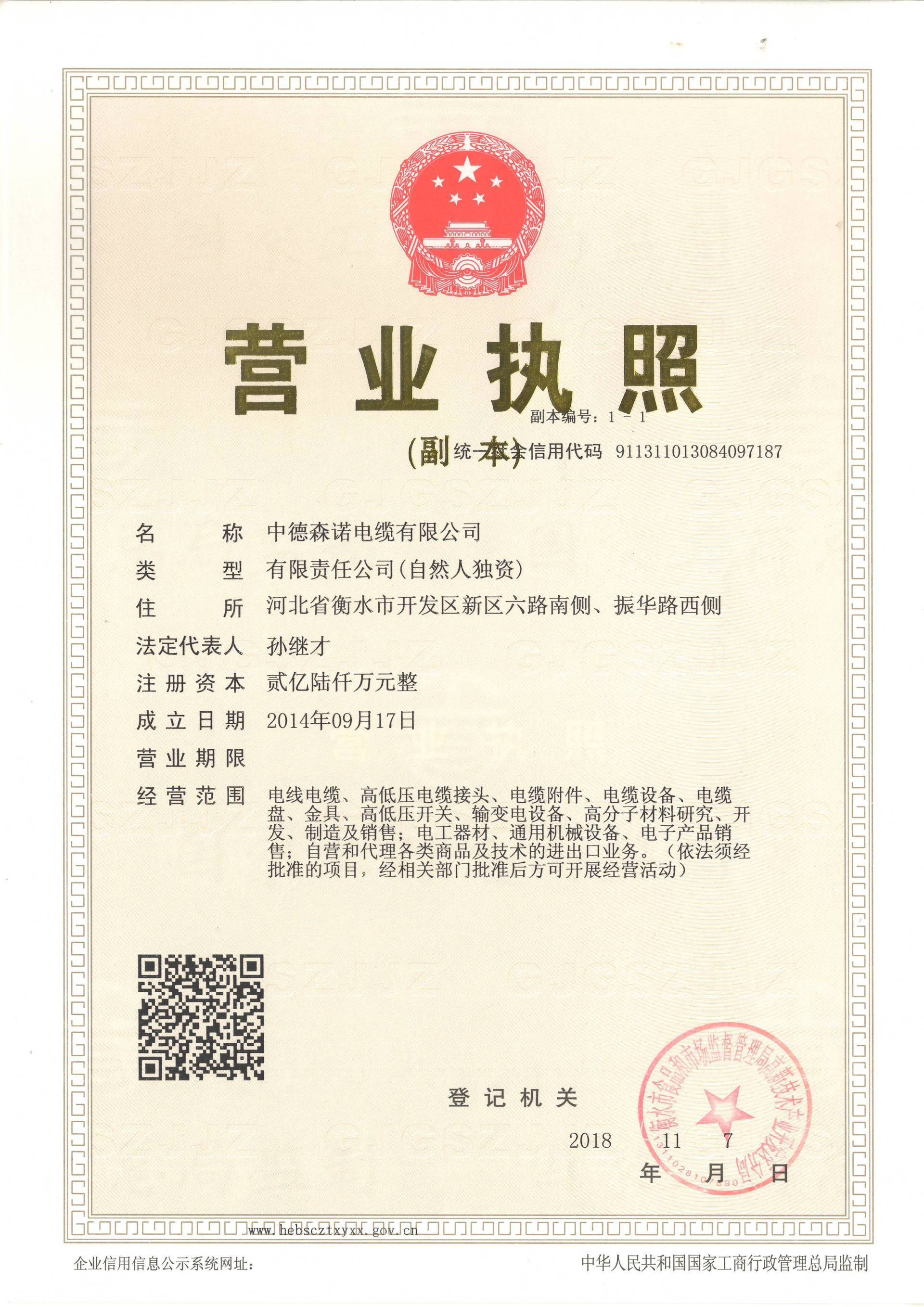
All rights reserved© Sennuo Sino-German Power by 300.cn | Business License
SEO


